Choosing an Off-Highway Machine Controller is more than matching a part number to a machine. On a loader, excavator, or other worksite vehicle, the controller must fit the electrical system, connected components, and operating demands. Dust, vibration, moisture, and temperature swings can all affect long-term performance. Small details count.
These seven tips will help you assess compatibility, control functions, communication protocols, environmental ratings, diagnostics, supplier support, and total ownership costs. Start with the machine’s documentation and confirm specifications with the equipment manufacturer or a qualified supplier. A familiar connector does not guarantee that a controller will communicate correctly or support the functions you need. Check how faults are reported, how updates are handled, and whether replacement units can be configured for your machine. Ask practical questions, too: Can technicians diagnose it on site? Are wiring diagrams and technical support available?
There is no universal best choice. A controller suited to one fleet may not suit another, even when the machines look similar. I have seen how an overlooked interface requirement can turn a promising purchase into extra workshop time. It is an easy detail to miss. Use the guidance below to compare options against real operating conditions, not just a product sheet. Careful verification cannot remove every risk, but it can make the decision clearer and more dependable.
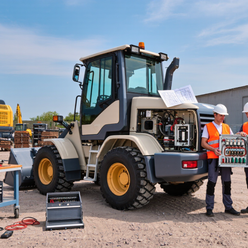
An off-highway machine controller is the machine’s decision point. It reads operator commands and sensor signals, then coordinates functions such as engine output, hydraulic flow, and implement movement. On a loader, for example, it may translate a joystick movement into valve commands while checking pressure and temperature. That distinction matters. The controller does not replace the operator; it helps the machine respond consistently to changing loads and conditions.
When choosing one, consider its role in the whole system, not just its processing speed. Check that it supports the required sensors and actuators, communicates reliably with other modules, and provides useful fault diagnostics. Dust, vibration, water, and temperature swings are everyday design conditions, not edge cases. A neat control map can still feel wrong at the joystick, so real-machine testing matters. Safe behavior during a sensor fault or power interruption matters, too.
The U.S. Bureau of Labor Statistics reported 5,283 fatal work injuries in 2023, with 1,942 involving transportation incidents in its Census of Fatal Occupational Injuries. Those figures cover all industries, not off-highway machines, but they underline why predictable motion and clear fault warnings deserve attention. A controller can support safer operation, but it cannot remove every hazard. Small details count: response delay, connector placement, and whether operators can understand an alert through cab noise. Be honest about trade-offs; more features can also mean harder troubleshooting.
Define the machine’s job before comparing controller features. A loader moving wet gravel has different control needs from a tracked carrier crossing rocky ground. List the functions the controller must manage, such as hydraulic valves, engine signals, display data, and safety interlocks. Be specific. Record the number and type of inputs and outputs, including spare capacity for likely attachments. A few extra channels may help later, but excess capacity can add cost and wiring complexity.
Describe the operating conditions with measurable details. Note expected temperature ranges, dust, water exposure, vibration, electrical supply, and available mounting space. Check where connectors sit: a plug facing a tire spray or trapped behind a hot panel can become a maintenance problem. Consider who will operate the machine, whether gloves are common, and how clearly faults must be shown. It is easy to overlook service access when reviewing a clean drawing. A practical assessment should include the duty cycle and a trial in realistic conditions, with the machine working and vibrating as it normally would. Some requirements will change after that test; document why, rather than treating the first specification as perfect.
| Tip | Requirements to Define | Operating Conditions to Consider | How to Verify the Fit |
|---|---|---|---|
| 1. Map the machine’s control functions | List the sensors, switches, actuators, displays, and safety-related functions the controller must support. Record required analog, digital, frequency, and output channels. | Account for simultaneous functions, startup sequences, operator inputs, and the consequences of a failed input or output. | Create an I/O schedule and check channel type, range, accuracy, current capacity, and available spare channels against the machine design. |
| 2. Match the electrical system | Specify nominal supply voltage, allowable operating range, peak loads, grounding arrangement, and protection needs. | Consider cranking voltage dips, alternator behavior, load switching, reverse-polarity risk, and electrical noise from motors or solenoids. | Compare the controller’s documented electrical limits with measured or established voltage conditions on the machine; assess transient protection as part of the system design. |
| 3. Select suitable communication interfaces | Identify the required network protocols, message rates, node count, diagnostic access, and connections to displays or other controllers. | Consider cable length, connector locations, network loading, electromagnetic interference, and whether equipment from different suppliers must communicate. | Confirm protocol compatibility and network capacity using interface documentation, a wiring plan, and a bench test with the intended network devices. |
| 4. Define temperature and environmental limits | Set the required operating and storage temperature ranges, plus any condensation, moisture, dust, or chemical exposure expectations. | Use the machine’s actual installation location: engine compartments, exposed chassis areas, wash-down zones, and locations near hot surfaces have different conditions. | Compare the controller’s published environmental ratings with the measured or specified conditions at the mounting point, including enclosure and connector protection. |
| 5. Assess vibration, shock, and mounting | Define mounting orientation, available space, connector clearance, and the mechanical loads the installation must tolerate. | Consider engine vibration, rough terrain, impact loads, frame flex, and vibration transmitted through brackets or nearby structures. | Review applicable test evidence and validate the proposed mounting arrangement on the machine. Use a suitable bracket and strain relief for wiring. |
| 6. Plan operator interaction and service access | Specify the information operators need, required controls or indicators, diagnostic access, and service procedures. | Consider visibility in daylight, use with gloves, cab or outdoor installation, cleaning practices, and access for inspection or replacement. | Evaluate the complete installation with representative operators and service personnel; check readability, reach, connector access, and fault-diagnosis workflow. |
| 7. Set safety, reliability, and lifecycle needs | Document failure responses, diagnostic requirements, availability expectations, software update needs, and expected service life. | Consider the machine’s duty cycle, remote or seasonal use, maintenance intervals, and the effect of a controller fault on machine operation. | Review system-level risk assessments, fault-handling behavior, support documentation, and replacement plans. Validate safety functions at the machine level. |
Compatibility starts at the connector, not the catalog. List each sensor’s signal type, voltage range, and fault behavior. A pressure sensor may use 0–10 V, while a speed pickup may send pulses. Confirm the controller accepts both, including required pull-ups and input filtering. Small details matter.
For actuators, check output current, PWM frequency, and whether a valve needs proportional control or simple on/off switching. Then verify network support: CAN-based protocols such as SAE J1939, plus the required message rates and diagnostic data. Shared connectors do not guarantee shared signals.
MarketsandMarkets estimated the industrial automation market at US$205.5 billion in 2022 and projected US$265 billion by 2027. That broad forecast is not proof that one controller fits every off-highway machine. It does underline the growing importance of connected systems.
Ask suppliers for protocol versions, bus-load limits, and fault-response details; “supports CAN” is not enough. Test the actual sensor and actuator set on a prototype, including cold starts and noisy electrical conditions. Record readings beside the machine’s wiring diagram. Even a careful checklist can miss a hidden mismatch, so leave time for bench testing before installation.
A controller’s performance is more than processing speed. Check response time under vibration, heat, and low-voltage starts, then test it with the actual sensors and actuators. A delayed alarm can matter when a machine is reversing near workers. The U.S. Bureau of Labor Statistics recorded 738 fatal workplace injuries involving contact with objects and equipment in 2022. That figure covers many hazards, not controllers alone, but it underlines why clear fault alerts and predictable shutdown behavior deserve practical testing. ISO 19014 provides a risk-based framework for functional safety in earth-moving machinery control systems. Ask for evidence that the controller and its safety functions were assessed for the machine’s intended use.
Environmental ratings need equally close reading. Under IEC 60529, IP6X means dust-tight, while IPX7 covers temporary immersion under specified test conditions. Neither rating proves resistance to pressure washing, chemical exposure, or constant vibration. Check the test conditions against the machine’s real cleaning routine. EPA’s Tier 4 nonroad diesel standards target roughly 90% lower particulate matter and 50% lower nitrogen oxides than earlier standards; a controller does not certify engine emissions, but its temperature and fault monitoring can support reliable operation. One trade-off is easy to miss: a tightly sealed enclosure can still overheat. Review the supplier’s temperature limits, mounting guidance, and test records, then verify them in the machine.
A controller must fit the machine’s electrical and communication architecture, not just its feature list. Compare its inputs, outputs, connector types, and network protocols with the existing wiring diagrams. A mismatch can mean extra adapters, altered harnesses, or time-consuming troubleshooting in the field. Ask how the controller handles sensor faults and whether diagnostic data can be read with tools already used by service technicians. Check that connectors are sealed against dust and moisture, and that mounting points can tolerate regular vibration. Small details matter. A bench test with representative sensors and actuators can reveal integration problems before installation, though it may not reproduce every condition on a working machine.
Serviceability becomes clear when something fails far from the workshop. Look for accessible connectors, replaceable components, clear fault codes, and setup instructions that do not depend on one person’s memory. Confirm what training, repair documentation, and spare parts will be available throughout the machine’s expected service life. Ask how software updates are delivered and whether older configurations remain supported. A low purchase price can be misleading if diagnosis requires long delays or specialist help. Support promises also deserve careful checking; written response times and parts availability are more useful than vague assurances. Even a well-tested controller can surprise you in harsh conditions, so leave room in the evaluation for field feedback and revisions.
Confirm its signal type, voltage range, and fault behavior. A pressure sensor may output 0–10 V; a speed pickup may send pulses.
Shared connectors do not guarantee matching signals. Check pull-ups, input filtering, and the controller’s accepted signal types.
Compare output current and PWM frequency. Check whether a valve needs proportional control or simple on/off switching.
Confirm the protocol version, message rates, bus-load limits, and diagnostic data. “Supports CAN” is not enough.
Test the actual sensors and actuators, including cold starts and electrical noise. Record readings beside the wiring diagram.
Check connector types, sealed enclosures, and mounting points. Dust, moisture, and regular vibration can expose weak spots.
Look for accessible connectors, clear fault codes, replaceable parts, and setup instructions. A technician may be far from the workshop.
Ask about training, repair documents, spare parts, software updates, and older configurations. Get response times in writing.
No. It may miss harsh field conditions. I might overlook a mismatch too, so leave time for field feedback and revisions.
Choosing the right Off-Highway Machine Controller starts with understanding the machine’s role and the tasks it must perform. Consider operating conditions such as temperature, vibration, moisture, dust, and expected workloads, then define the required control functions, response times, and future capacity. These details help narrow the options and avoid selecting a controller that is either insufficient for the job or unnecessarily complex.
Next, verify that the controller can communicate reliably with the machine’s sensors, actuators, and networks. Compare processing performance, safety features, and environmental ratings against the demands of the application. Also consider how easily the controller can be integrated, configured, diagnosed, and serviced. Clear documentation, accessible technical support, and long-term parts availability can reduce downtime and simplify maintenance. By evaluating these factors together, operators and engineers can make a practical choice that supports dependable performance throughout the machine’s service life.